Description
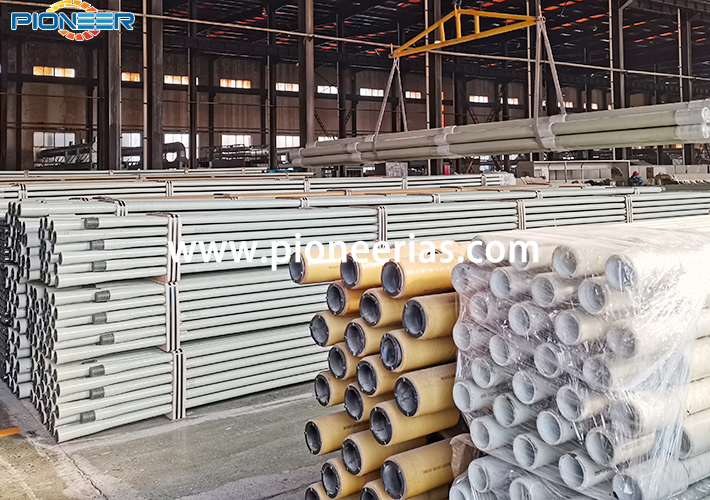
High Pressure GRE Line Pipe
GRE Line Pipe mainly serves the following:
Transportation line for oil, gas, water and other fluids in Oil & Gas and PetroChemical.
Being of excellent performance on
Corrosion resistance;
Insulation;
Easy installation;
Light weight (the weight is 30% of the same size steel pipe);
Fluidity (the inner wall roughness is 10% of the same size steel pipe);
Low thermal conductivity (thermal conductivity is 0.6% of the steel pipe).
Diameter: DN40-DN900;
Pressure rating: 3.45-34.5MPa;
Product Standard
API 15HR-2016 Specification for High Pressure Fiberglass Line Pipe
Product Properties | Amine epoxy GRE line pipe | Acid anhydride GRE line pipe | |
Temperature Resistant Level | Medium temperature | ≤ 93.3℃ | ≤ 65.5℃ |
Physical Properties | Density | 1.95 g/cm³ (121.74 lbs./ft3) | 1.95 g/cm³ (121.74 lbs./ft3) |
Specific gravity | 1.95 | 1.95 | |
Thermodynamic Properties | Heat conductivity coefficient | 0.40W/m℃ (0.23 BTU/ft/hr/°F) | 0.40W/m℃ (0.23 BTU/ft/hr/°F) |
Linear expansion coefficient | 15.8×10⁻⁶mm/mm℃ (8.8×10⁻⁶in/in/°F) | 14×10-6mm/mm℃ (6.1×10⁻⁵in/in/°F) | |
Flow Coefficients | Hazen-Williams factor | C =150 | C =150 |
Absolute roughness | 0.0053mm (0.00021") | 0.0053mm (0.00021") | |
Elastic Coefficients | Hoop elastic modulus | 22.8GPa (3.2×10⁶psi) | 24.1GPa (3.5×10⁶psi) |
Axial elastic modulus | 12.6GPa (1.82×10⁶psi) | 11.9GPa (1.7×10⁶psi) | |
Poisson ratio (minimum) | 0.38 | 0.38 | |
Size | Pressure Rating | Thread | Nominal ID | Nominal Wall thickness | Minimum Bending Radius | Nominal Length | ||
mm | in | MPa | PSI | in | mm | mm | meter | meter |
DN65 | 2 1/2 | 7 | 1000 | 2 7/8”EUE | 60 | 2.6 | 48 | 9 |
8.5 | 1250 | 60 | 3.3 | 48 | 9 | |||
10 | 1500 | 60 | 4.0 | 50 | 9 | |||
12 | 1750 | 60 | 5.3 | 50 | 9 | |||
14 | 2000 | 60 | 5.9 | 50 | 9 | |||
16 | 2300 | 60 | 6.6 | 52 | 9 | |||
18 | 2600 | 60 | 7.3 | 52 | 9 | |||
20 | 2900 | 60 | 8.6 | 52 | 9 | |||
22 | 3200 | 60 | 9.2 | 54 | 9 | |||
DN80 | 3 | 7 | 1000 | 3 1/2”EUE | 76 | 3.3 | 60 | 9 |
8.5 | 1250 | 69 | 4.0 | 60 | 9 | |||
10 | 1500 | 69 | 5.3 | 60 | 9 | |||
12 | 1750 | 69 | 5.9 | 60 | 9 | |||
14 | 2000 | 69 | 7.3 | 62 | 9 | |||
16 | 2300 | 69 | 8.6 | 62 | 9 | |||
18 | 2600 | 69 | 9.6 | 64 | 8.8 | |||
20-JG | 2900 | 69 | 12.0 | 66 | 8.8 | |||
DN100 | 4 | 5.5 | 800 | 4 1/2”EUE | 94 | 3.3 | 74 | 8.8 |
7 | 1000 | 94 | 4.0 | 74 | 8.8 | |||
8.5 | 1250 | 94 | 5.3 | 74 | 8.8 | |||
10 | 1500 | 94 | 6.6 | 74 | 8.8 | |||
12 | 1750 | 94 | 7.9 | 76 | 8.8 | |||
14 | 2000 | 94 | 9.2 | 76 | 8.8 | |||
16-JG | 2300 | 94 | 10.6 | 76 | 8.8 | |||
DN150 | 6 | 3.5 | 500 | EUE 7” | 148.6 | 3.3 | 110 | 8.7 |
5.5 | 800 | 148.6 | 5.2 | 110 | 8.7 | |||
7 | 1000 | 148.6 | 6.6 | 112 | 8.7 | |||
8.5-JG | 1250 | 135 | 8.6 | 112 | 8.7 | |||
10-JG | 1500 | 135 | 9.8 | 112 | 8.7 | |||
12-JG | 1750 | 135 | 11.5 | 112 | 8.7 | |||
DN200 | 8 | 3 | 400 | EUE 8 5/8” | 194 | 4.0 | 130 | 8.6 |
4.5 | 650 | 194 | 5.9 | 130 | 8.6 | |||
6 | 850 | 194 | 7.3 | 135 | 8.6 | |||
7-JG | 1000 | 194 | 8.5 | 135 | 8.6 | |||
8.5-JG | 1250 | 209 | 11.2 | 140 | 8.6 | |||
10-JG | 1500 | 209 | 13.2 | 140 | 8.6 | |||
DN250 | 10 | 3.5 | 500 | T-thread | 250 | 5.3 | 155 | 11.2 |
5.5 | 800 | 250 | 8.5 | 160 | 11.2 | |||
7 | 1000 | 250 | 11.0 | 165 | 11.2 | |||
8.5 | 1250 | 250 | 13.3 | 175 | 11.2 | |||
DN300 | 12 | 3.5 | 500 | T-thread | 300 | 6.4 | 185 | 11.2 |
5.5 | 800 | 300 | 10.1 | 190 | 11.2 | |||
7 | 1000 | 300 | 13.0 | 195 | 11.2 | |||
8.5 | 1250 | 300 | 16.0 | 200 | 11.2 | |||
DN400 | 16 | 3.5 | 500 | T-thread | 400 | 13.0 | 255 | 11.2 |
DN500 | 20 | 3.5 | 500 | T-thread | 500 | 16.0 | 320 | 11.2 |
DN600 | 24 | 3.5 | 500 | T-thread | 580 | 18.5 | 370 | 11.2 |
Note: 1. JG=Coupled, without JG means the connection is integral joint.
2. Other sizes could be designed and customized as per customers' requirements.


